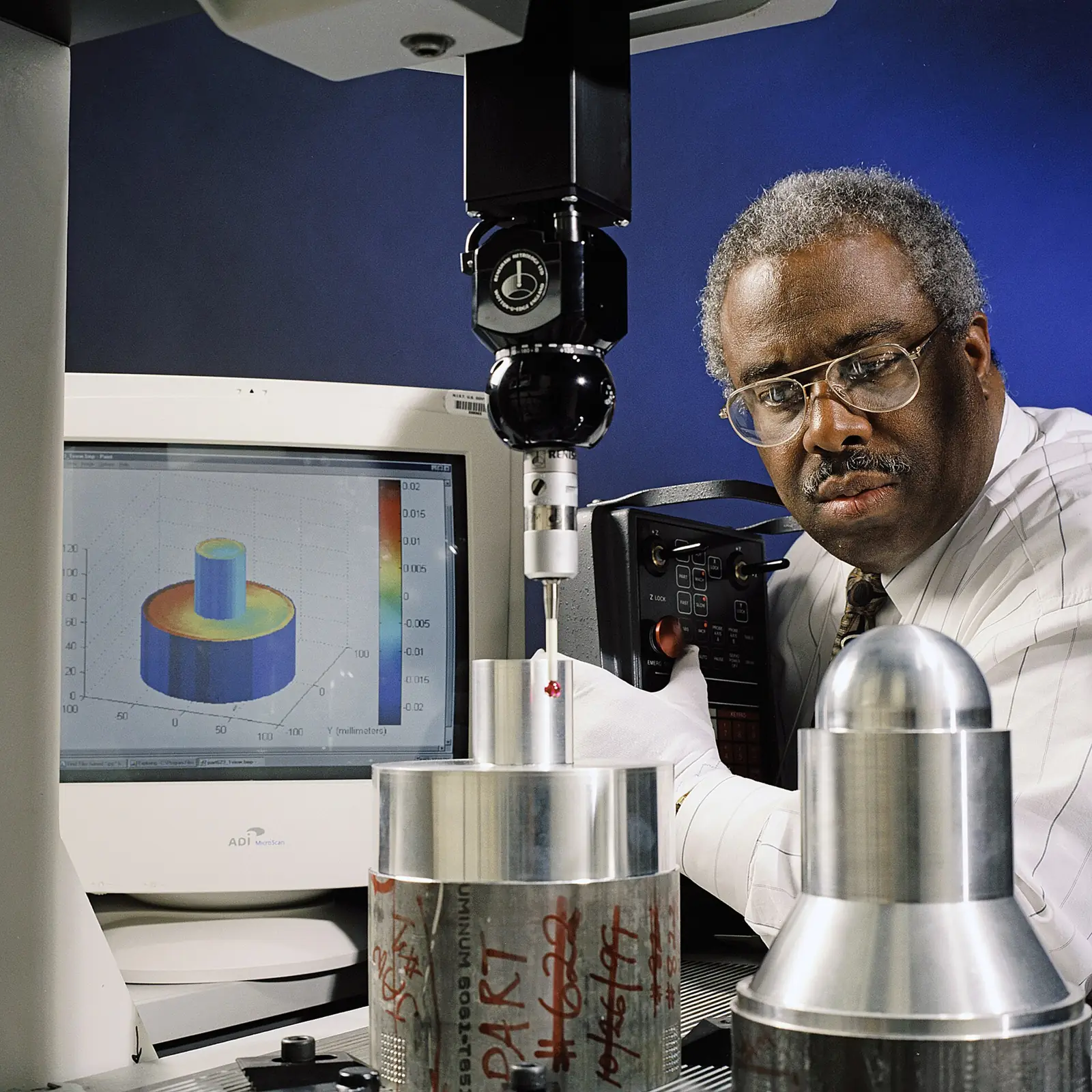
Engineer operating a coordinate measuring machine on a machined part
All machine vision applications
Machine Vision · Metrology

Vision-Based Dimensional Measurement and Gauging

Vision-based measurement checks the dimensions of parts without touching them: lengths, diameters, hole positions, radii, gaps and profiles. Because it is fast, it can measure every part in-line instead of a sample in the lab, and every value is logged for statistical process control.

Dimensional Measurement at a glance

What it measures
Length, width, diameter, hole position, angle, radius, gap, flushness, height and profile.
How it measures
Telecentric lenses and backlight for 2D silhouettes, and laser triangulation for 3D profiles and heights.
How it is trusted
Calibration against certified targets and a gauge R&R study before the system is released.
What you get
Pass or fail on every part, and measurement data for SPC and capability studies.
Definition

What is vision-based dimensional measurement?

Dimensional measurement confirms that a part is the size and shape the drawing says. Traditionally that means callipers, gauges or a coordinate measuring machine in the quality lab, on a sample of parts.

Vision-based measurement uses calibrated cameras and optics to measure edges and features in an image with sub-pixel precision. It measures in milliseconds and without contact, so it can check every part on the line.

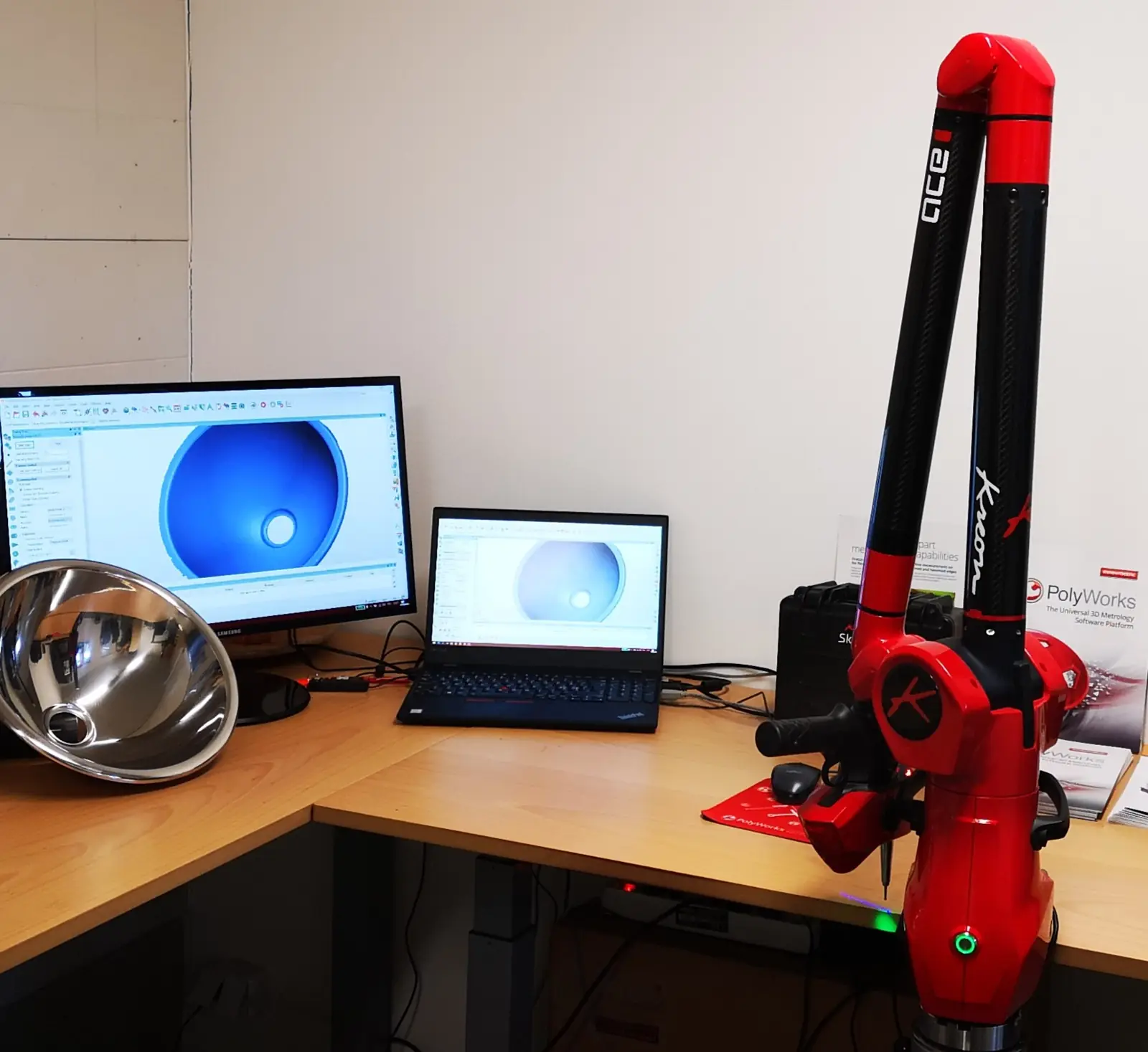
Portable measuring arm next to a computer showing a scanned part
Lab metrology sets the reference. In-line vision measurement carries it to every part on the production line.
The problem

Why sampling is not enough

  • Sampling a few parts per shift can let a whole batch of bad parts through between checks.
  • Manual gauging depends on the operator and is slow for multi-feature parts.
  • Soft, hot or delicate parts cannot always be touched.
  • A drifting tool or mould is only noticed after parts are already out of tolerance.
  • Handwritten readings rarely make it into useful process data.
How it works

How dimensional measurement works, step by step

STEP 1PresentSTEP 2ImageSTEP 3MeasureSTEP 4DecideSTEP 5Log
  1. STEP 1

    Present the part

    Parts pass on a conveyor, sit in a fixture, or are placed by a robot in the measuring field.

  2. STEP 2

    Capture a precise image

    A telecentric lens with a backlight produces a sharp silhouette with no perspective error; a laser line gives height and profile in 3D.

  3. STEP 3

    Measure the features

    Edges are found to a fraction of a pixel and converted to millimetres using the calibration.

  4. STEP 4

    Compare with tolerance

    Each feature is compared with its nominal and tolerance, and the part passes or fails.

  5. STEP 5

    Feed SPC

    Every value is stored so trends, Cp and Cpk can be tracked and tools adjusted before parts go out of tolerance.

The technology

Methods that make it reliable

Telecentric optics

A telecentric lens keeps magnification constant with distance, so a part measures the same size even if it sits slightly higher or lower in the field.

Backlight silhouettes

Lighting the part from behind turns its outline into a high-contrast edge that can be measured very precisely.

3D laser triangulation

A laser line projected onto the part is viewed at an angle; its shape gives the height profile, used for depth, flatness, gaps and flushness.

Measurement system analysis

Calibration with certified targets and a gauge R&R study show how much of your tolerance the system uses, before anyone relies on it.

Capabilities

What it can check

  • Length and width
  • Inner and outer diameters
  • Hole position and pitch
  • Angles and radii
  • Thread presence
  • Gap and flush
  • Height and depth
  • Flatness and warp
  • Profile against CAD
Industries

Where it is used

Automotive componentsRubber and plastic mouldingMachined metal partsElectronics and connectorsMedical devicesPackaging components
Sample projects

How a project is scoped

Two example project scopes showing how the station, the checks and the outputs are defined. Every plant is different, so the final configuration is confirmed after a feasibility study on your own parts.

Example scope · Moulded parts

In-line diameter and hole checks on moulded components

The situation: A moulder checks a handful of parts per shift with callipers and has shipped out-of-tolerance batches.

Station
Telecentric camera and backlight over the moulding machine outfeed
Measures
Outer diameter, hole diameter and hole position on every part
Output
Pass or fail with rejection, SPC chart per cavity
Extra
Alert when one mould cavity starts drifting
Example scope · Extruded profiles

Continuous profile measurement on an extrusion line

The situation: An extruder measures its profile by cutting samples, and scraps metres of product before a drift is found.

Station
Laser profile sensors around the moving profile
Measures
Width, wall thickness and profile shape continuously
Output
Live profile against the nominal, alarm on tolerance breach
Extra
Measurement record per metre for the customer
What is in the system

Typical components

  • High-resolution monochrome area-scan cameras
  • Telecentric lenses
  • Collimated backlights
  • 3D laser profile sensors
  • Certified calibration targets
  • SPC software and data export

Cameras and lenses, supplied locally

Industrial cameras, lenses, line-scan cameras and code readers are available through our machine vision catalog, quoted with delivery to Sri Lanka. We select the hardware for your application during the feasibility study.

Browse the hardware catalog
How we work

Proven on your parts before you commit

Every product, surface and line behaves differently under a camera, so every project starts with evidence from your own material.

  1. PHASE 1

    Discovery

    A site visit to understand your product, line speed, quality criteria and where the check should sit.

  2. PHASE 2

    Feasibility study

    We image your good and defective samples and show what the system can reliably detect. This is the go or no-go.

  3. PHASE 3

    Pilot station

    One station on one line, running beside your inspectors until results match and your team trusts them.

  4. PHASE 4

    Rollout and support

    More lines, integration with your PLC and systems, and local support from our Sri Lankan engineering team.

FAQ

Dimensional Measurement: common questions

How accurate is machine vision measurement?

+

It depends on the field of view, camera resolution, optics and lighting. Accuracy is designed around your tolerance: as a rule of thumb, the measurement system should use only a small fraction of the tolerance band, which is verified with a gauge R&R study before production.

Why use a telecentric lens for measurement?

+

A normal lens makes objects look bigger when they are closer. A telecentric lens keeps magnification constant over a range of distances, so small changes in part height do not change the measured size.

Can vision measure in 3D?

+

Yes. Laser triangulation and structured light sensors measure height, depth, flatness and profile, for example gaps and flushness between assembled parts or the height of components on a board.

Does in-line measurement replace our CMM?

+

No. The CMM stays as the reference for complex geometry and first-article inspection. In-line vision measures the critical features on every part, which a CMM cannot do at production speed.

Can measurement data go to our quality system?

+

Yes. Values can be exported to your SPC or quality software, or to a database or spreadsheet, and trends and capability indices can be shown on the line.

Send us a few sample parts

Tell us what you need to check and share some good and faulty samples. We will show you what a camera can reliably see before you commit to anything.

Photographs show representative plants and equipment, not Cerox installations or client sites. Diagrams by Cerox Engineering. Photo credits, via Wikimedia Commons: Coordinate measuring machine by National Institute of Standards and Technology, Public domain; Portable measuring arm by TestoCH, CC BY-SA 4.0.