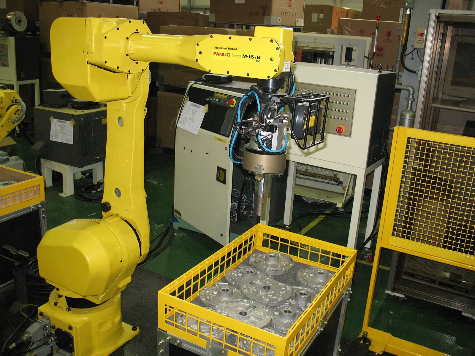
Industrial robot picking parts from a crate inside a safety cell
All machine vision applications
Machine Vision · Robotics

Vision-Guided Robotics and Bin Picking

Vision-guided robotics uses 2D or 3D cameras to tell a robot exactly where each part is and how it is oriented, so the robot can pick parts that are not precisely positioned: off a moving conveyor, out of a tray, or jumbled in a bin. It removes the need for expensive fixtures and part feeders.

Vision-Guided Robotics at a glance

What it enables
Picking from conveyors, trays and bins, packing, kitting, palletising, depalletising and machine tending.
How it sees
2D cameras for flat parts in known planes, 3D structured light, stereo or time-of-flight sensors for bins and stacks.
How it connects
Hand-eye calibration links camera coordinates to the robot, with encoder tracking for moving conveyors.
What you get
Flexible automation that handles mixed parts and positions without re-tooling.
Definition

What is vision-guided robotics?

A robot on its own repeats taught positions precisely, but it is blind: the part must be exactly where it expects. Vision-guided robotics adds a camera that finds each part and sends its position and orientation to the robot, so the robot adapts its path every cycle.

2D vision is enough when parts lie flat on a conveyor or tray. 3D vision measures depth as well, which is needed to pick randomly stacked parts from a bin, known as bin picking, or to unload mixed cartons from a pallet.

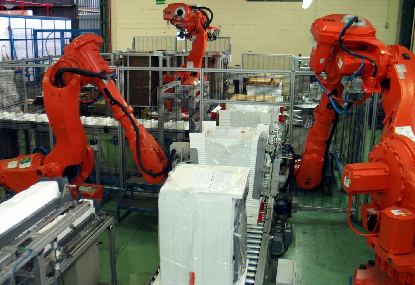
Industrial robots packing products in an automated packing cell
Robots in a packing cell. With vision, the same cell can handle products that arrive in any position.
The problem

Why blind robots are limited

  • Precise fixtures and feeders are expensive and must change for every new part.
  • Parts arriving on a conveyor are rarely in exactly the same place.
  • Manual picking from bins and trays is repetitive, tiring work.
  • Mixed-product lines need automation that adapts without re-tooling.
  • Labour shortages make flexible automation more valuable every year.
How it works

How vision-guided robotics works, step by step

STEP 1LocateSTEP 2PoseSTEP 3TransformSTEP 4PickSTEP 5Verify
  1. STEP 1

    Find the part

    A camera above the conveyor, tray or bin captures the scene and finds each part, in 2D or in 3D.

  2. STEP 2

    Work out position and orientation

    Software calculates where the part is and how it is turned, and chooses a part the gripper can reach.

  3. STEP 3

    Convert to robot coordinates

    Hand-eye calibration converts camera coordinates into robot coordinates; an encoder adds conveyor movement.

  4. STEP 4

    Pick and place

    The robot plans a collision-free path, picks the part and places it in the target position.

  5. STEP 5

    Check the result

    The camera can confirm the pick succeeded and the part was placed correctly before the next cycle.

The technology

Methods that make it reliable

2D localisation

Pattern matching finds flat parts on a conveyor or tray and gives their X, Y position and rotation to the robot.

3D sensing

Structured light, stereo cameras or time-of-flight sensors produce a point cloud so the robot can pick parts stacked or jumbled in a bin.

Hand-eye calibration

A calibration routine precisely relates the camera to the robot, whether the camera is fixed above the work area or mounted on the robot arm.

Conveyor tracking

An encoder on the conveyor lets the robot pick moving parts by predicting where each part will be when the gripper arrives.

Capabilities

What it can check

  • Parts on moving conveyors
  • Parts in trays and blister packs
  • Randomly placed parts in bins
  • Mixed cartons on pallets
  • Machine loading and unloading
  • Kitting of mixed components
  • Orientation before assembly
  • Pick confirmation
  • Placement verification
Industries

Where it is used

Food packingAutomotive componentsLogistics and warehousingElectronics assemblyMetal and plastic partsPharmaceuticals
Sample projects

How a project is scoped

Two example project scopes showing how the station, the checks and the outputs are defined. Every plant is different, so the final configuration is confirmed after a feasibility study on your own parts.

Example scope · Food packing

Conveyor picking into trays

The situation: A food producer packs products into trays by hand at the end of a production line.

Station
Camera over the conveyor, delta or SCARA robot with conveyor tracking
Vision
2D localisation of each product, position and rotation
Output
Products placed in the tray pattern, rejects left to pass
Extra
Product quality check in the same image before picking
Example scope · Machine tending

Bin picking to load a machine

The situation: A component maker loads machined blanks into a machine by hand from a bulk bin.

Station
3D sensor over the bin, industrial robot with a custom gripper
Vision
Point cloud part localisation and grasp planning
Output
Blanks loaded into the machine without an operator
Extra
Regrip station to correct orientation when needed
What is in the system

Typical components

  • 2D area-scan cameras
  • 3D structured light or stereo sensors
  • Industrial or collaborative robot
  • Custom grippers and vacuum tools
  • Conveyor encoder
  • Safety fencing or scanners

Cameras and lenses, supplied locally

Industrial cameras, lenses, line-scan cameras and code readers are available through our machine vision catalog, quoted with delivery to Sri Lanka. We select the hardware for your application during the feasibility study.

Browse the hardware catalog
How we work

Proven on your parts before you commit

Every product, surface and line behaves differently under a camera, so every project starts with evidence from your own material.

  1. PHASE 1

    Discovery

    A site visit to understand your product, line speed, quality criteria and where the check should sit.

  2. PHASE 2

    Feasibility study

    We image your good and defective samples and show what the system can reliably detect. This is the go or no-go.

  3. PHASE 3

    Pilot station

    One station on one line, running beside your inspectors until results match and your team trusts them.

  4. PHASE 4

    Rollout and support

    More lines, integration with your PLC and systems, and local support from our Sri Lankan engineering team.

FAQ

Vision-Guided Robotics: common questions

What is bin picking?

+

Bin picking is a robot picking parts that are randomly piled in a bin. It needs 3D vision to measure where each part is and how it lies, and software that chooses which part the gripper can reach without collisions.

Do we need 2D or 3D vision?

+

Use 2D when parts lie flat in a known plane, such as on a conveyor or tray. Use 3D when parts are stacked, jumbled or vary in height, such as in a bin or on a mixed pallet.

Can vision work with our existing robot?

+

Usually, yes. Most industrial and collaborative robots accept position data from a vision system. We check the robot model and controller during the feasibility study.

What is hand-eye calibration?

+

It is the procedure that relates the camera to the robot so that a position found in the image converts into the exact position the robot should move to. It is done when the cell is commissioned and checked whenever the camera or robot is moved.

Can a robot pick moving parts from a conveyor?

+

Yes. With conveyor tracking, an encoder measures belt movement so the robot knows where each located part will be when the gripper reaches it.

Send us a few sample parts

Tell us what you need to check and share some good and faulty samples. We will show you what a camera can reliably see before you commit to anything.

Photographs show representative plants and equipment, not Cerox installations or client sites. Diagrams by Cerox Engineering. Photo credits, via Wikimedia Commons: Robot picking from a crate by Mixabest, CC BY-SA 3.0; Robotic packing cell by Tecnowey, CC BY-SA 3.0.